A guide to developing electronic based systems – Part 3
Part 3 – Electronic hardware design
Custom built hardware design is so common that the general public don’t really notice it. Phones, TVs, dishwashers; essentially all everyday appliances and a lot more besides; rely on electronics that has been designed specifically for purpose.
Moreover, visibility of how the electronics is designed is very low. The construction of say houses and bridges is easy to see; the function of, or reason for the build is apparent. Electronics however is often hidden, masked by the functional skin of the product it will control or power. The design of it can easily be ignored or remain a mystery. This article provides an overview of some of the important elements of hardware design.
To set the scene for this article, we provide four definitions.
Schematic: A diagram which represents the design of the electronic system. The diagram shows the components that provide the functionality required and connectivity between them.
PCB layout: A design created from a schematic which can be printed onto a board so as to provide electrical connections between the components of the design.
Discrete components: The simplest of components that can be used to create an electronic based system. At least one of the components in an electronic design needs to be active, i.e. it can control an electric current.
Integrated circuits: Complex components which perform the same function as a group of discrete components.
Electronic design is both a science and an art. On the face of it, it’s simple; the schematic design captures the logic based on available components, and the PCB layout provides the physical form to which the components can be attached. What can go wrong?
Never underestimate the challenges to be faced when designing electronics. Every minor detail matters from the exact rating of a component to the length of a track on the PCB.

To a first order if the circuit logic is correct then the electronics will work as expected and work every time. But real world disturbances and the limitations of component operation may mean this is not the case. The following provides some tips from designers to help make the job easier.
Decoupling: This is the process of smoothing signals to ensure that voltages stay in the correct range for the components on the board. If not present, components may become damaged or may have their lifetimes shortened. The scenario is similar to the fluctuations and drop in pressure that can occur if you run a tap downstairs whilst someone is taking a shower upstairs. The two situations need to be decoupled. Sources and causes of fluctuations are topics for more detailed papers but including decoupling components in the design will keep things running more smoothly.
Designing for EMC: Electromagnetic Capability is a topic worthy of its own paper. But the biggest issues arise if engineers defer addressing it until late in the project. EMC should be considered from the start. Consideration should be given to areas that are likely to emit signals as well as areas that will be susceptible to disturbance from other signals. Power supplies, crystals and oscillators are the main sources of emissions, essentially any area involved with switching. They may also be susceptible. Filtering signals, smoothing signals and applying signal screens are all options, as is giving proper attention to placing susceptible components away from emitting ones and routing vulnerable tracks internally when designing the PCB.
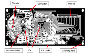
Floating inputs: Microcontrollers (MCUs), e.g. Synergy processors, are used to house the software logic which will control the functions of the board. Pins on the MCU provide connections between the software and the hardware electronics. In operation they will be set either in a logic 1 or a logic 0 state (on or off). The software will read the state of the pins when requested and perform functions according to the state read. Figure 1 shows microcontroller pins and looking carefully it can be seen that not all pins are connected to the board. This means their state may be undefined which could lead the software into performing incorrectly. To avoid potential unexpected behaviour these pins will need to be fixed to either one or the other states. Many MCU’s, including Synergy, provide support for this within the processor; software is provided to set initial states; but the hardware engineer needs always to check. Collaboration with the software engineer about how to initialise the hardware and how to handle is recommended. In particular caution should be used when powering-up a board before software initialisation has occurred. Make sure that the point at which floating inputs are set is known and be aware of possible adverse behaviour before this point.
Minimising power consumption: Controlling power consumption is a cooperative effort between hardware and software engineers. Often with hardware there is no magic method for dramatically reducing current draw but by making small reductions here and there the cumulative effect can produce valuable rewards. Consider whether or not the MCU can run off a reduced supply voltage or if the processing speed can be lowered. Select components that work off the widest set of possible voltage ranges as this will provide more options for the design. In particular review the currents flowing through resistors. If this can be minimised the combinatorial effect can produce some significant savings. Engage with the software engineer to optimise the design for say MCU usage. If for example the processor can be put to sleep for periods of time this could save power, but possibly extra hardware may be required to ensure the correct wake-up sequence. The Synergy S1 range is specifically designed with low power options in mind. It has a number of low power modes allowing engineers to select which parts of the processor are awake at any one time.
Liaising with other engineering disciplines throughout the design process, and in particular working alongside the software engineers will lead to a more optimal design.
> For an overview of Renesas Synergy MCUs, click here: https://www.renesas.com/en-eu/products/synergy/microcontrollers.html
Article series by:
Dr Val Lynch Dr. Val Lynch, CEO von AND Technology Research
Steve Norman, Manager Global Ecosystems, Renesas Electronics Europe


