
Functional Safety for Integrated Circuits by Tom Meany – Analog Devices, Inc.
Integrated circuits (ICs) are at the root of all modern safety systems. Integrated circuits supply the logic and either control the sensors or, to a growing extent, are the sensors. Integrated circuits drive the final elements to achieve a safe state and they are the platform on which the software runs. The level of integration possible within semiconductors can simplify the system-level implementation at the cost of the added complexity within the IC itself. This level of integration gives improvements in system reliability due to part count reduction and offers opportunities for increased diagnostic coverage with lower diagnostic test intervals—all at a cost that makes safety affordable. It could be argued that this level of integration is a bad thing because of the added complexity. However, with the price of complexity in the integrated circuits can come a major simplification at the module and system levels. Surprisingly, while there are functional safety standards that address process control, machinery, elevators, variable speed drives, and toxic gas sensors, there is no functional safety standard dedicated to integrated circuits. Instead, bits and pieces of the requirements and knowledge are spread around IEC 61508 and other Level B and C standards. This article gives guidance on interpreting the existing functional safety standards for semiconductors.
Introduction
Typically, integrated circuits are developed to either IEC 61508 or ISO 26262. In addition, there are sometimes additional requirements in the level two and level three standards. Developing and assessment to the functional safety standards are what give the confidence that these sometimes complex integrated circuits are sufficiently safe. When IEC 61508 was written it was targeted at bespoke systems, as opposed to open market mass produced integrated circuits. This article will review and comment on the known functional safety requirements for integrated circuits. While the article concentrates on IEC 61508 and its application in industrial sectors, much of the material is relevant to applications such as automotive, avionics, and medical.
Functional Safety
Functional safety is the part of safety that deals with confidence that a system will carry out its safety related task when required to do so. Functional safety is different from other passive forms of safety such as electrical safety, mechanical safety, or intrinsic safety.
Functional safety is an active form of safety; for example, it gives confidence that a motor will shut down quickly enough to prevent harm to an operator who opens a guard door or that a robot will operate at a reduced speed and force when a human is nearby.
Standards
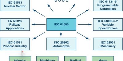
The key functional safety standard is IEC 61508.1 The first revision of this standard was published in 1998 with revision two published in 2010 and work beginning in 2017 to update to revision three with a probable completion date of 2022. Since the first edition of IEC 61508 was published in 1998, the basic IEC 61508 standard has been adapted to suit fields such as automotive (ISO 26262), process control (IEC 61511), PLC (IEC 61131-6), IEC 62061(machinery), variable speed drives (IEC 61800-5-2), and many other areas. These other standards help interpret the very broad scope of IEC 61508 for these more limited fields.
Some functional safety standards such as ISO 13849 and D0-178/D0-254 have not been derived from IEC 61508. Nevertheless, anybody familiar with IEC 61508 and reading these standards would not be too surprised by the contents.
Within a safety system, it is the safety functions that perform the key functional safety activities when the system is running. A safety function defines an operation that must be carried out to achieve or maintain safety. A typical safety function contains an input subsystem, a logic subsystem, and an output subsystem. Typically, this means that a potentially unsafe state is sensed, and something makes a decision on the sensed values and, if deemed potentially hazardous, instructs an output subsystem to take the system to a defined safe state.
Figure 1. A sample of functional safety standards.

The time between the unsafe state existing to achieving a safe state is critical. A safety function might, for instance, consist of a sensor to detect that a guard on a machine is open, a PLC to process the data, and a variable speed drive with a safe torque off input that kills a motor before a hand inserted in a machine can reach the moving parts.
Safety Integrity Levels
SIL stands for safety integrity level and is a means to express the required risk reduction needed to reduce the risk to an acceptable level. According to IEC 61508, the safety levels are 1, 2, 3, and 4, with an order of magnitude increase in safety as you go from one level to the next. SIL 4 is not seen in machinery and factory automation where generally no more than one person is typically exposed to a hazard. It is rather reserved for applications like nuclear and rail where hundreds or even thousands of people can be hurt. There are also other functional safety standards such as automotive, which uses ASIL (automotive safety integrity levels) A, B, C, and D and ISO 13849. Its performance levels a, b, c, d, and e can be mapped to the SIL 1 to SIL 3 scale.
Table 1. Rough Correspondence of Safety Levels Across Application Areas
The author is not convinced that a claim of greater than SIL 3 is possible for a single IC. However, it is noted that the tables in Annex F of IEC 61508-2:2010 show a SIL 4 column.
The Three Key Requirements
Functional safety imposes three key requirements on the development of ICs. These requirements are explored in the following sections.
Requirement 1—Follow a Rigorous Development Process
IEC 61508 is a full lifecycle model. It covers all the phases from safety concept, to requirements capture, to maintenance, and, eventually, to the disposal of the item. Not all of these phases are relevant to an integrated circuit and training and experience are required to identify those that are. IEC 61508 offers a V model for an ASIC and, along with the review, audit, and other requirements in IEC 61508, it represents a system that, while it cannot guarantee safety, has been shown to generate safe systems and ICs in the past.
Most IC manufacturers already have rigorous new product development standards because of the high cost of changing a faulty integrated circuit. A set of masks alone for a low geometry process can cost over $500k. This and the long lead times already force integrated circuit designers to implement a rigorous development process with good verification and validation stages. One of the big differences for functional safety is that safety must not alone be achieved but must also be demonstrated so that even the best IC manufacturers will be required to add a safety process on top of their normal development process to ensure that the correct evidence of compliance is created and archived.
Faults introduced by the development process are referred to as systematic faults. These are faults that can only be fixed through a design change. These faults can include faults related to requirements capture, insufficient EMC robustness, and insufficient testing.
Annex F of IEC 61508-2:2010 lists a set of dedicated measurements that the experts on the IEC committee deemed suitable for use to develop integrated circuits. Table F.2 applies to FPGA and CPLD, while table F.1 applies to digital ASICs. The measures are given as R (recommended) or HR (highly recommended), depending on the SII and, in some cases, alternative techniques are offered. Very few of the requirements should be of much surprise to an IC supplier with a good development process, but the requirement for 99% stuck at fault coverage for SIL 3 is challenging, especially for small digital or mixed-signal parts where a lot of the circuitry is at the periphery of the block. The requirements in revision two of the standard are only for digital ICs, but many can also be applied to analog or mixed-signal ICs (the next revision of ISO 26262 will contain similar tables and has versions for analog and mixed-signal integrated circuits).
In addition to tables F.1 and tables F.2, there is some introductory text that also gives insights. For instance, in this introductory text is an allowance to use proven in use tools and it offers a suggestion of 18 months of use across projects of similar complexity as being reasonable. This means that the full tool requirements from IEC 61508-3 need not apply.
A proven in use claim may be available to module/systems designers if they have successfully used an IC in the past and know the application and the failure rate from the field. This claim is much harder for integrated circuit designers or manufacturers to make as they generally do not have enough knowledge of the final application or what percentage of the failing units from the field are returned to them for analysis.
Software
All software errors are systematic because software does not age. Therefore any on-chip software should consider the requirements of IEC 61508-3. Typically, on-chip software might include a kernel/bootloader on a microcontroller/DSP. However, in some cases the microcontroller/DSP could contain a small microcontroller preprogrammed by the IC manufacturer to implement a block of logic instead of using a state machine. This preprogrammed microcontroller software would also need to meet the requirements of IEC 61508-3. Application level software is typically the responsibility of the module/system designer as opposed to the IC manufacturer, but the IC supplier may need to provide tools such as compilers or low level drivers. If those tools are used in the development of safety related application software then the IC manufacturer would need to supply enough information for the end user to meet the tool requirements in IEC 61508-3:2010 clause 7.4.4.
The author has also programmed in C and in many other programming languages. He has done a limited amount of Verilog programming. Verilog and its sister VHDL are examples of two HDLs (hardware definition languages) used to design digital integrated circuits. The question as to whether an HDL is software is an interesting one, but for now following IEC 61508-2:2010 Annex F is sufficient. In practice the author has found that if Annex F is followed then in combination with the other requirements of IEC 61508 (the life cycle phases, etc.) it doesn’t really matter whether HDL is considered as software or not, as the developer still ends up doing all the required tasks. A related interesting standard is IEC 62566,2 which deals with safety functions for the nuclear industry developed using an HDL.
Requirement 2—Be Inherently Reliable
IEC 61508 imposes reliability requirements in the form of a PFH (average frequency of dangerous failure per hour) or PFD (probability of failure on demand). These limits are tied to an adult’s risk of dying from natural causes and the idea that going to work or about your daily business should not significantly increase this. The maximum PFH for a SIL 3 safety function is 10–7/h or a dangerous failure rate of approximately once per 1000 years. Expressed as FIT (failure in time/failure per billion hours of operation), this is 100 FIT.
Given that a typical safety function has an input block, a logic block, and an actuator block, and that the PFH budget must be allocated across all three blocks, it is entirely possible that the PFH for a given IC can be in single digits (<10 FIT). Redundant architectures can be used to allow higher numbers so that two items of 100 FIT each can give equivalent confidence to one item with a reliability of 10 FIT limited by CCF (common cause failure) concerns. However, redundancy consumes a lot of space and energy, and adds to the cost.
IC manufacturers such as Analog Devices supply reliability information for all their released ICs on sites such as analog.com/reliabilitydata, based on accelerated life testing. This is sometimes frowned upon because the reliability evaluation is done in a lab under artificial conditions. Instead, the use of industry-wide standards such as SN 295003 or IEC 623804 are recommended. These standards, however, have a number of issues:
- υ They predict reliability at the 99% confidence level and IEC 61508 only requires data at the 70% confidence level and so the standards are pessimistic.
- υ They mix random and systematic failure modes. These are meant to be dealt with differently under IEC 61508.
- υ They are not frequently updated.
- υ They make no allowance for the quality differences between suppliers.
What standards such as SN 29500 do demonstrate is how reliable on-chip transistors really are. If two ICs of 500k transistors each are used to implement a safety function they would have a FIT of 70 each for a total system FIT of 140. However, if the two ICs are replaced by one IC of one million transistors, the FIT for that one IC is only 80, which is a reduction of over 40%.
Soft errors are often neglected within ICs. Soft errors are different from traditional reliability predictions in that they disappear once the power is cycled. They are caused by neutron particles from space or alpha particles from the packaging material striking on-chip RAM cells or flip-flop (FF) and changing the stored value. ECC (double bit error detect and single bit error correction) can be used to detect and seamlessly correct errors in RAMs but at a cost of reduced speed and higher on-chip errors. Parity adds less overhead but leaves the system designer to solve the error recovery issue. If parity or ECC techniques are not used, the soft error rate can exceed the traditional hard error rate by up to a factor of 1000 (IEC 61508 offers a figure of 1000 FIT/MB for RAMs). The techniques available to address soft errors in the FF (flip-flops) used to implement logic circuits are not as satisfactory but watchdog timers, time redundancy in calculations, and other techniques can help.
Requirement 3—Be Fault Tolerant
No matter how reliable the product, bad things will sometimes still happen. Fault tolerance accepts this reality and then addresses it. Fault tolerance has two main elements. One is the use of redundancy and the other is the use of diagnostics. Both accept that failures will occur no matter how good the reliability of the ICs or the development process used to develop the IC.
Redundancy can be identical or diverse, and it can be on-chip or off-chip. Annex E of IEC 61508-2:2010 offers a set of techniques to demonstrate that sufficient measures have been taken to support claims for on-chip redundancy in digital circuits using nondiverse redundancy. Annex E appears to have been targeted at dual lock-step microcontrollers and no guidance is given for on-chip independence for
- υ Analog and mixed-signal integrated circuits
- υ Between an item and its on-chip diagnostics
- υ Digital circuits employing diverse redundancy
However, in some cases Annex E can be intelligently interpreted for these cases. An interesting item within Annex E is the βIC calculation, which is a measure of on-chip common cause failures. It allows a judgment of sufficient separation provided the sources of common cause failure represent a β of less than 25%, which is high in comparison to the 1%, 5%, or 10% found in the tables of IEC 61508-6:2010.
Diagnostics are an area in which integrated circuits can really shine. On-chip diagnostics can
- υ Be designed to suit the expected failure modes of the on-chip blocks
- υ Add no PCB space due to the limited requirement for external pins
- υ Operate to a high rate (minimum diagnostic test interval)
- υ Obviate the need for redundant components to implement diagnostics by comparison
This means that on-chip diagnostics can minimize the system cost and area. Generally the diagnostics are diverse (different implementation) to the item they monitor on-chip and so it is unlikely they will fail in the same way and at the same time as the item they are monitoring. When they do, it is likely that they would have the same issues (often related to EMC, power supply issues, and over temperature) even if the diagnostics were implemented in a separate chip. While the standard does not contain the requirement, there are concerns related to using on-chip power supply monitors and watchdog circuits, which are diagnostics of last resort. Some external assessors will insist on such diagnostics being off-chip.
Generally, the diagnostics on simpler integrated circuits will be controlled by a remote microcontroller/DSP with measurements done on-chip but the results shipped off-chip for processing.
IEC 61508 requires minimum levels of diagnostic coverage given as SFF (safe failure fraction), which considers safe and dangerous failures and is related but different from DC (diagnostic coverage), which neglects safe failures. The measure of success of the implemented diagnostics can be measured using a quantified FMEA or FMEDA. However, the diagnostics implemented within an IC can also cover components external to the IC and items within the IC can be covered by system-level diagnostics. When an IC developer performs the FMEDA, the assumption must be given that the IC developer doesn’t generally know the details of the final application. In ISO 26262 terminology, this is known as an SEooC (safety element out of context). For end users to make use of the IC-level FMEDA, they must satisfy themselves that the assumptions still hold for their system.
While Table A.1 (and indeed Tables A.2 to A.14) of IEC 61508-2:2010 give good guidance on the IC faults that should be considered when analyzing an IC, an even better discussion of the topic is given in Annex H of IEC 60730:2010.5
Development Options for an Integrated Circuit
There are several options for developing integrated circuits to be used in functionally safe systems. There is no requirement in the standard to only use compliant integrated circuits, but rather the requirement is that the module or system designers satisfy themselves that the chosen integrated circuit is suitable for use in their system.
The available options include
- υ Developing fully in compliance to IEC 61508 with an external assessment and safety manual
- υ Developing in compliance to IEC 61508 without external assessment and with a safety manual
- υ Developing to the semiconductor companies’ standard development process but publish a safety data sheet
- υ Developing to the semiconductor companies’ standard process
Note—for parts not developed to IEC 61508, the safety manual may be called a safety data sheet or similar to avoid confusion with parts developed in compliance to a safety manual.
Option 1 is the most expensive option for semiconductor manufacturers, but also offers potentially the most beneficial to module or system designers. Having such a component where the application shown in the safety concept for the integrated circuits matches that of the system reduces the risk of running into problems with the external assessment of the module or system. The extra design effort for a SIL 2 safety function can be on the order of 20% or more. The extra effort would probably be higher, except that semiconductor manufacturers typically already imply a rigorous development process even without functional safety.
Option 2 saves the cost of external assessment but otherwise the impact is the same. This option can be suitable where customers are going to get the module/system externally certified anyway and the integrated circuit is a significant part of that system.
Option 3 is most suitable for already released integrated circuits where the provision of the safety data sheet can give the module or system designer access to extra information that they need for the safety design at the higher levels. This includes information such as details of the actual development process used, FIT data for the integrated circuit, details of any diagnostics, and evidence of ISO 9001 certification for the manufacturing sites.
Option 4 will, however, remain the most common way to develop integrated circuits. Use of such components to develop safety modules or systems will require additional components and expense for the module/ system design because the components will not have sufficient diagnostics requiring dual-channel architecture with comparison as opposed to single-channel architectures. Without a safety data sheet, the module/ system designer will also need to make conservative assumptions and treat the integrated circuit as a black box.
In addition, semiconductor companies need to develop their own interpretations of the standards and the author’s own company has developed internal documents ADI61508 and ADI26262 for this purpose. ADI61508 takes the seven parts of IEC 61508:2010 and interprets the requirements in terms of an integrated circuit development.
A SIL 2/3 Development
Sometimes an integrated circuit can be developed to all the systematic requirements per SIL 3. This means all of the relevant items from table F.1 of IEC 61508-2:2010 for SIL 3 are observed and that all of the design reviews and other analyses are done to a SIL 3 level. However, the hardware metrics may only be good enough for SIL 2. Such a circuit could be identified as a SIL 2/3 or more typically SIL M/N, where the M represents the maximum SIL level that can be claimed in terms of the hardware metrics and the N the maximum SIL level that can be claimed in terms of the systematic requirements. Two SIL 2/3 integrated circuits can be used to implement a SIL 3 module or system because having two SIL 2 items in parallel upgrades the combination to SIL 3 in terms of hardware metrics, but each item is already at SIL 3 in terms of the systematic requirements. If instead the integrated circuits were only SIL 2/2, putting two such integrated circuits in parallel would still not make it SIL 3 as it would be SIL 3/2 at the best.
Applying the Hardware Metrics to an Integrated Circuit
Except in cases where almost the entire safety function is implemented by an integrated circuit, it is very hard to specify SFF, DC, or PFH limits to a semiconductor. Taking SFF as an example, while the SFF is required to be greater than 99% for SIL 3, this applies to the entire safety function rather than the integrated circuit. If the integrated circuit comes in at 98%, it can still be used to implement a SIL 3 safety function, but other parts of the system will need to achieve a higher coverage to compensate. The safety manual or safety data sheet for the integrated circuit needs to publish the λDD, λDU, and λ for use in the system-level FMEDA.
Ideally, the IC requirements would be derived for a system-level analysis, but often this is not the case and the development is effectively an SEooC (see ISO 26262) or a safety element out of context. In the case of an SEooC, the IC developer needs to make assumptions about how the IC will be used in systems. The system or module designer must then compare these assumptions to their real system to see if the functional safety of the IC is sufficient for their system. These assumptions can decide whether a diagnostic is implemented on the IC or at the system level and so impact on IC-level features and capabilities.
Security
A system cannot be safe unless it is also secure. Presently the only guidance in IEC 61508 or ISO 26262 related to security is to refer the reader to the IEC 62443 series.6 However, IEC 62443 appears to be more targeted at larger components, such as entire PLC components, rather than to individual ICs. The good news is that most of the requirements in the functional safety standards to eliminate systematic faults also apply to security. The lack of any references is interesting because, in some cases, hardware can supply a hardware root of trust and features like a PUF (physically unclonable function), which is important for safety and security.
Conclusions
The existing IEC 61508 covers everything from developing an integrated circuit to an oil refinery. While there are dedicated sector specific standards for such areas as machinery and process control, and, while there is some guidance in IEC 61508 revision two for integrated circuits, there is no standard specific to integrated circuits. The lack of specific requirements leaves the requirements open to interpretation and therefore conflicts can arise between the expectations of multiple customers and external assessors.
This means that sectors will be inclined to make sector specific requirements for integrated circuits in their higher level standards. Such requirements can already be seen in standards such as EN 50402,7 but most especially in the 2016 draft of ISO 26262,8 where a new part, part 11, deals specifically with integrated circuits.
It is the author’s hope that revision 3 of IEC 61508, due to be published sometime around 2021, will expand and clarify the guidance on integrated circuits. The author is lucky to be part of IEC TC65/SC65A MT61508-1/2 and MT 61508-3, and so will, therefore, get a chance to participate in such endeavors. Perhaps a future revision might have a part 8 dedicated just to semiconductors so that there is consistency across the sectors, allowing integrated circuits to be developed that meet the requirements of all the sectors.
Even then it is unlikely that the standard will contain everything that an IC manufacturer needs to design an IC with functional safety requirements. Requirements related to security, EMC, etc., will still need to be derived from systems application knowledge.
References
1 IEC 61508:2010: Functional Safety of Electrical/Electronic/Programmable Electronic Safety-Related Systems. International Electrotechnical Commission, 2010.
2 IEC 62566:2012: Nuclear Power Plants—Instrumentation and Control Important to Safety—Development of HDL-Programmed Integrated Circuits Performing Category A Functions. International Electrotechnical Commission, 2012.
3 SN 29500-2: Expected Values for Integrated Circuits. Siemens, 2010.
4 IEC TR 62380:2004: Reliability Data Handbook—Universal Model for Reliability Prediction Of Electronic Components, PCB, and Equipment. International Electrotechnical Commission, 2004.
5 IEC 60370-1:2010: Automatic Electrical Controls for Household and Similar Use—Part 1: General Requirements. International Electrotechnical Commission, 2010.
6 ISA/IEC 62443: Industrial Communication Networks—Networks and Systems Security. International Society of Automation and International Electrotechnical Commission.
7 EN 50402:2016: Electrical Apparatus for the Detection and Measurement of Combustible or Toxic Gases or Vapours or Oxygen—Requirements on the Functional Safety of Gas Detection Systems. European Committee for Standards—Electrical, 2016.
8 ISO 26262:2011: Road Vehicles Functional Safety. International Organization for Standardization, 2011.
About the Author
Tom is a 30 year veteran of Analog Devices and he holds a B.Eng. first class in electronics and an M.Sc. first class in applied mathematics and computing. Tom is the holder of eight U.S. patents and is a certified TÜV Rheinland functional safety engineer in the area of machinery. Tom is a member of various IEC working groups in the area of functional safety, including those related to IEC 61508-2, IEC 61508-3, and IEC 61800-5-2. He can be reached at tom.meany@analog.com.
Download PDF here ……………… A54121 Functional-Safety-For-Integrated-Circuits