Gaining Better System Performance, Fault Protection, and Speed from RS-485 ICs
Since the RS-485 standard was approved in March of 1998, it has become an extremely popular solution for a broad range of industrial equipment. Unlike “standards” such as Ethernet or IO-Link, which define connector types, cables, and data protocols, RS-485 is just a physical layer specification allowing user flexibility over how it is implemented in end systems. Since many applications are closed systems or proprietary, rather than requiring inter-operability, engineers have found solutions to go beyond the original specification defined in 1998. This article examines the advantages of the RS-485 standard and takes a look at how new RS-485 ICs have evolved to deliver enhanced system performance, fault protection, and speed.
Introduction
There are various serial interfaces, ranging from RS-232 to multi-Gigabit Ethernet and beyond. Though each protocol suits a particular application, in all cases cost and performance of the physical layer (PHY) must be considered. This article focuses on the RS-485 interface and the applications best suited to that standard. It also shows the ways that optimization of data rates as a function of cabling, system design, and component selection can be done. Since RS-485 devices are often used in closed or proprietary communication interfaces, this article also presents solutions that go beyond the original standard to offer the engineer higher performance and a high level of robustness while maintaining backward compatibility with older RS-485 products.
RS-485 Standard: Ideal for Industrial Applications
The ANSI/TIA/EIA-485-A-1998 (commonly known as RS-485) standard was approved in March of 1998 to address several shortcomings of RS-232 and RS-422. RS-485 is a bidirectional, half- or full-duplex standard featuring multiple ‘bussed’ drivers and receivers, in which each driver can relinquish the bus. It meets all RS-422 specifications, but is more robust. It has higher receiver-input impedance and larger common-mode range (-7V to +12V). Table 1 lists the key specifications in the original RS-485 standard.
RS-485 is an electrical-only standard (PHY) using differential signaling for noise immunity, typically on a balanced transmission cable such as unshielded twisted pair (UTP). With a -7V to +12V bus common-mode range, receiver input sensitivity is ±200mV, which means that to recognize a mark or space, a receiver must see signal levels above +200mV or below -200mV. Minimum receiver input impedance is 12kΩ, and the driver output voltage is ±1.5V minimum, ±5V maximum.
RS-485 allows a multi-point operation, or bus topology. To be standards-compliant, the driver must be able to drive up to 32 “unit loads” (UL), i.e., 32 12kΩ receivers in parallel. For receivers of higher input impedance, the number of unit loads on one bus can be higher. Any number of receivers can be connected to the bus, provided that the combined (parallel) load presented to the driver does not exceed 32 UL (375Ω). The driver load impedance is 54Ω maximum, which, in a typical 24AWG twisted-pair environment, is 32 UL in parallel with two 120Ω terminators. In industrial applications, the wide common-mode range enables data transmission over longer cable lengths and in noisy environments such as the floor of a factory. Also, the receivers’ higher input impedance allows more devices to be dropped on the lines.
|
RS-485 Standard |
|
|
Signalling |
Differential |
|
Duplex |
Half and full duplex |
|
Maximum cable length |
4000ft (1.2km) |
|
Data rates |
Up to 100Mbps |
|
Driver differential output into 54Ω |
±1.5V |
|
Driver maximum differential output |
±6V |
|
Driver maximum short-circuit current |
250mA |
|
Driver minimum differential load |
54Ω |
|
Receiver single-ended input resistance (1UL) |
≥12kΩ |
|
Receiver input voltage range |
-7V to +12V |
|
Receiver differential input high |
≥200mV |
|
Receiver differential input low |
≤200mV |
Table 1. RS-485 Specifications
Full and Half Duplex
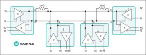
RS-485 was originally defined as a half-duplex interface as shown in Figure 1, building on RS-422’s use of a single twisted pair for communication, but allowing the driver to relinquish the signal line so another device may take over as the transmitter and the original device could now receive. This allowed for two-way communication between two RS-485 devices. However, due to the shared channel, the two devices are not able to talk simultaneously and, thus, any real-time control must happen unidirectionally. The introduction of full-duplex signaling allows for two RS-485 devices to both transmit and receive at the same time, at the cost of having a separate channel for each direction. However, this implementation of a full-duplex system is different from wiring two RS-422 systems in opposite directions as each driver retains the ability to relinquish the channel, which allows for multi-drop full-duplex systems to be realized. Any full-duplex RS-485 system can also be easily reconfigured for half-duplex operation by connecting the channel to both the transmit and receive inputs.
Figure 1. A Half-Duplex Transceiver
Cable Length and Construction
As the channel of communication, the properties of the signal-carrying cable are vitally important for successful transmission. The longer the cable, the greater the attenuation of the original signal, as well as an increased susceptibility to electrical noise. The specifications of RS-485 were originally made to combat this weakness.
RS-485 is designed to be a balanced system. Simply put, this means there are two wires, other than ground, that are used to transmit the signal (Figure 2).
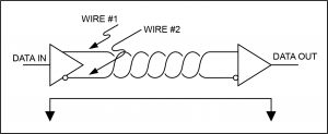
Figure 2. A balanced system uses two wires, other than ground, to transmit data.
The system is called balanced because the signal on one wire is ideally the exact opposite of the signal on the second wire. In other words, if one wire is transmitting a high, the other wire will be transmitting a low, and vice versa. Although RS-485 can be successfully transmitted using multiple types of media, it should be used with wiring commonly called “twisted pair.”
Cable Length and Speed
The original definition of RS-485 capped the maximum data rate at 10Mbps. Modern systems, however, require several times that in reliable communication speed. Techniques such as preemphasis have evolved to tackle the inherent drawbacks of operating at such high frequencies. For more details on this topic, please refer to these application notes: “How Far and How Fast Can You Go with RS-485?” and “Preemphasis Improves RS-485 Communications.”
Preemphasis
The combination of the line loss and transmission line effects results in a trade-off between cable length and data rate. Faster data rates necessarily have faster transitions. The cable’s transmission line effects attenuate the high frequency components of these transitions such that when the signal arrives at the receiver, the sharp edges of the signal have rounded off. In severe cases, this could make transmission impossible. In addition to this, the wide frequency content of fast transitions cause intersymbol interference (ISI), which distorts the message. One way to combat these issues is to introduce preemphasis to RS-485.
IR Losses and Jitter Impose Limits
The two major effects that limit the maximum length for a given type of transmission line in RS-485 communications are current-times-resistance (IR) losses and signal jitter. Transmission-line resistance is usually negligible in comparison with termination resistance at the end of the line. However, when transmission lines are greater than 4000ft, line resistance cannot be ignored. IR losses result from the resistor divider, which consists of the cable resistance and the termination resistor. These losses diminish the signal magnitude by -6dB at 4000ft (down 50%) for a PVC-insulated, #24 AWG twisted-pair cable with a characteristic impedance of 100Ω.
Signal jitter is primarily due to ISI. ISI is the net effect of several causes of signal degradation. One cause is the attenuation and the dispersal of frequency components that result from signal propagation down a transmission line. Another cause is the variation of rise and fall times that follow the varying sequences of ones and zeros known as “pattern-dependent skew.” A data pulse responds to these effects with a loss of amplitude, displacement in time, rounded edges, and a “smearing” of the pulse into adjacent time slots, or unit intervals.
For a fixed amount of jitter (10%), the cable-length-versus-data-rate curves exhibit a “breakpoint” that represents the cable’s bandwidth at the receiving end after 4000ft. This breakpoint occurs at data-rate values that depend on the shape and the slew rate of the signal at the transmitting end. Because of the cascaded lumped-element network of the cable, the rolling-off slopes are identical. Thus, one way to extend distance for a given data rate is by reducing the effect of jitter that ISI causes. Preemphasis provides such a reduction; preemphasis pushes the curve to the right, enhancing reliable communications by increasing the allowable maximums for data rate and transmission distance.
The effect of preemphasis depends greatly on the signal data rate and the length of the cable being used for transmission. If the cable is too short or the data rate too low, the distortion caused by ISI is negligible and, thus, preemphasis will have little effect on signal quality while consuming more power. Conversely, with long cables and fast data rates, preemphasis will greatly improve signal fidelity and offer a much better Unit Interval (UI) than without. In each case, the amount of preemphasis will vary depending on the application.
What Is Twisted Pair and Why Is It Used?
As its name implies, a twisted pair is simply a pair of wires of equal length and twisted together. Using an RS-485-compliant transmitter with twisted-pair wire reduces two major sources of problems for designers of high-speed long-distance networks: radiated electromagnetic interference (EMI) and received EMI.
Radiated EMI
High-frequency components are present whenever fast edges are used in transmitting information. These fast edges are necessary at the higher data rates at which RS-485 is capable of transmitting. The resultant high-frequency components of these fast edges coupled with long wires can radiate EMI. A balanced system used with twisted-pair wire reduces this effect by making the system an inefficient radiator. It works on a very simple principle: as the signals on the wires are equal but opposite, the radiated signals from each wire will also tend to be equal but opposite. This has the effect of canceling each other, meaning that there is no net-radiated EMI. However, this result is based on the assumption that the wires are exactly the same length and in exactly the same location. Because it is impossible to have two wires in the same location at the same time, the wires should be positioned as close to each other as possible. Twisting the wires so there is a finite distance between the two wires helps counteract any remaining EMI.
Received EMI
Received EMI is basically the same problem as radiated EMI but in reverse. The wiring used in an RS-485 system will also act as an antenna that receives unwanted signals. These unwanted signals could distort the desired signals, which, if bad enough, can cause data errors. For the same reason that twisted-pair wire helps prevent radiated EMI, it also helps reduce the effects of received EMI. Because the two wires are close together and twisted, the noise received on one wire will tend to be the same as that received on the second wire. This type of noise is referred to as “common-mode noise.” As RS-485 receivers are designed to look for signals that are the opposite of each other, they can easily reject noise that is common to both.
Shielding
Another layer of protection can be added by enclosing the twisted pair in a metallic foil or braided wire shield. This layer is grounded on either side of the connection and works to isolate the signal wires inside the cable from the environment. Adding shielding, therefore, addresses both radiated and received EMI, but also adds a significant amount of weight and cost to the cable, as now there is more conductor along the cable.
Characteristic Impedance of Twisted-Pair Wire
Depending on the geometry of the cable and the materials used in the insulation, twisted-pair wire will have a “characteristic impedance” associated with it that is usually specified by its manufacturer. The RS-485 specification recommends, but does not specifically dictate, that this characteristic impedance be 120Ω. Recommending this impedance is necessary to calculate worst-case loading and common-mode voltage ranges given in the RS-485 specification. The specification probably does not dictate this impedance in the interest of flexibility. If for some reason 120Ω cable cannot be used, it is recommended that the worst-case loading (the number of transmitters and receivers that can be used) and worst-case common-mode voltage ranges be recalculated to make sure that the system under design will work. The industry-standard publication TSB89, Application Guidelines for TIA-EIA-485-A, has a section specifically devoted to those calculations.
Termination Resistors
Because of the high frequencies and the distances involved, proper attention must be paid to transmission-line effects. A thorough discussion of transmission-line effects and proper termination techniques is, however, well beyond the scope of this article. With this in mind, terminations will be briefly discussed in their simplest form as they relate to RS-485.
A terminating resistor is simply a resistor placed at the extreme end or ends of a cable (Figure 3). The value of the terminating resistor is ideally the same value as the characteristic impedance of the cable.

Figure 3. Termination resistors should be the same value of the characteristic impedance of the twisted pair and should be placed at the far ends of the cable.
When the termination resistance is not the same value as the characteristic impedance of the wiring, reflections will occur as the signal travels down the cable. This process is governed by the equation (RT – Zo)/(Zo + RT), where Zo is the impedance of the cable and RT is the value of the terminating resistor. Although some reflections are inevitable due to cable and resistor tolerances, large enough mismatches can cause reflections big enough to cause errors in the data.
Knowing this about reflections, it is important to match the terminating resistance and the characteristic impedance as closely as possible. The position of the terminating resistors is also very important. Termination resistors should always be placed at the far ends of the cable.
Robustness
The RS-485 definition includes minimal protection requirements for the data line itself. If the system is implemented as defined by the standard, severe voltage and current surges along the line can damage the transmitters and receivers. This vulnerability makes the interface unsuitable for applications where large spikes in voltage can occur with relative frequency, such as lightning strikes for a building control system, or ESD from a busy industrial floor.
Fail-safe Inputs
In addition to this vulnerability, RS-485 does not specify what the system will do in the event that the inputs are open or shorted, and in this situation the receiver would be in an unknown state, creating transmission hazards that could cause false signaling and system lockup. By implementing a fail-safe on the receiver, the device can be driven to a known output state. This prevents inserting spurious signals on the receiver output.
Hot-swap
When circuit boards are inserted into a hot or powered backplane, differential disturbances to the data bus can lead to data errors. Upon initial circuit-board insertion, the data communication processor undergoes its own power-up sequence. During this period, the processor’s logic-output drivers are high impedance and unable to drive the enable inputs (DE and RE) to a defined logic level. Leakage currents up to ±10μA from the high-impedance state of the processor’s logic drivers could cause standard CMOS enable inputs of a transceiver to drift to an incorrect logic level. Additionally, parasitic circuit board capacitance could cause coupling of VCC or GND to the enable inputs. Without the hot-swap capability, these factors could improperly enable a transceiver’s driver or receiver.
Fault Protection
Besides voltage spikes from ESD and power surges, harsh industrial environments introduce the possibility of input voltage faults. If for some reason the inputs of the transceiver are shorted to a voltage that exceeds the -7V to +12V maximum specified in the RS-485 standard, the transceivers will likely sustain damage from the overdriven inputs and could destroy the device completely. Fault protection can be implemented with external overvoltage protection circuits, but these will increase the loading on the signal line and degrade signal quality.
New RS-485 Transceiver Solutions
RS-485 continues to be a popular choice for many industrial automation and control applications, and many modern applications use RS-485 as their physical layer of communications. However, the requirements of these applications often exceed the specifications set by the original standard, and so multiple techniques have been developed to extend the usefulness of RS-485 beyond the original specifications. Maxim offers three new RS-485 transceiver solutions to extend the performance of RS-485 beyond its limits, as outlined in Table 2.
|
MAX14783E High Speed, ±35kV ESD |
MAX14775E ±65V Fault Protected |
MAX22500E / MAX22502E With Preemphasis |
|
|
Mode of Operation |
Half Duplex |
Half-Duplex |
Half-Duplex / Full Duplex |
|
Maximum Data Rate |
42Mbps |
20Mbps |
100Mbps |
|
Number of Drivers / Receivers |
32 (UL = 1) |
100 (UL = 1/3) |
Point-to-Point only |
|
Maximum Cable Length (UTP) |
Varies with data rate, up to 100kbps at 4000ft |
Varies with data rate, up to 100kbps at 4000ft |
100Mbs @ 100ft to 30Mbps @ 600ft, and up to 100kbps at 4000ft |
|
Receiver Input Range (VCM) |
-8V to +13V |
±65V Fault Protected |
±15V Common Mode Range |
|
Receiver Input Resistance |
12kΩ |
38kΩ |
10kΩ |
|
Fail Safe |
Integrated, RO logic high |
Integrated, RO logic high |
Integrated, RO logic high |
|
Fault Protected |
Integrated hot swap |
Fault Protected |
Integrated hot swap and fault protection |
Table 2. Maxim solutions to expand the capabilities of RS-485
MAX14783E
The MAX14783E is an RS-485 half-duplex transceiver capable of multi-drop operation at up to 42Mbps with ±35kV of integrated ESD protection and a true fail-safe. It presents a robust RS-485 solution for applications which could expect to suffer ESD or load faults on the RS-485 inputs and can continue through such an event without affecting normal behavior of the chip. MAX14783E is also hot-swappable, incorporating a hot-swap circuit to prevent undesired driver/receiver enable configurations.
Hot-Swap Input Circuitry
The DE and RE enable inputs feature hot-swap capability. At the input, there are two nMOS devices, M1 and M2 (Figure 4). When VCC ramps from 0V, an internal 10μs timer turns on M2 and sets the SR latch that also turns on M1. Transistors M2 (a 500μA current sink) and M1 (a 100μA current sink) pull DE to GND through a 5kΩ (typ) resistor. M2 is designed to pull DE to the disabled state against an external parasitic capacitance up to 100pF that can drive DE high. After 10μs, the timer deactivates M2 while M1 remains on, holding DE low against three-state leakages that can drive DE high. M1 remains on until an external source overcomes the required input current. At this time, the SR latch resets and M1 turns off. When M1 turns off, DE reverts to a standard, high-impedance CMOS input. Whenever VCC drops below 1V, the hot-swap input is reset. A complementary circuit employing two pMOS devices pulls RE to VCC.
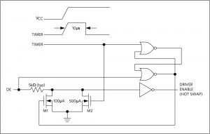
Figure 4. Simplified structure of MAX14783E driver enable (DE) pin supports hot-swap
±35kV ESD Protection
ESD protection structures are incorporated on all pins to protect against electrostatic discharges encountered during handling and assembly. The driver outputs and receiver inputs of the MAX14783E have extra protection against static electricity. The ESD structures withstand high ESD in all states: normal operation, shutdown, and powered down. After an ESD event, the MAX14783E keeps working without latch-up or damage.
MAX14775E
The MAX14775E is an RS-485 half-duplex transceiver capable of driving up to 100 unit loads at up to 20Mbps, with integrated protection to ensure reliable communications. This device uses a number of techniques to increase robustness including ±65V fault protection on driver outputs and receiver inputs, and ±25V common mode range on the receiver Inputs. The integrated fault protection prevents system damage during line faults and puts the receiver into a known state during which it periodically checks the line for the fault condition, while otherwise isolating the receiver from the damaging fault. This integrated solution provides robust communication while not compromising the integrity of the RS-485 signal and also eliminates the cost of providing an external fault protection circuit.
±65V Fault Protection
The driver outputs/receiver inputs of transceivers connected to an industrial RS-485 network often experience faults when shorted to voltages that exceed the -7V to +12V input range specified in the EIA/TIA-485 standard. Under such circumstances, ordinary RS-485 transceivers that have a typical absolute maximum voltage rating of -8V to +12.5V require costly external protection devices which can compromise the RS-485 performance. To reduce system complexity and the need for external protection, the driver outputs/receiver inputs of the MAX14775E are designed to withstand voltage faults of up to ±65V with respect to ground without damage. Protection is guaranteed regardless of whether the transceiver is active, in shutdown, or without power. When a fault is detected on A or B, the affected driver output is switched into a high-impedance state. After 300ms (typ), the driver output is re-enabled for 30μs (typ). If the fault condition persists, the driver output is again disabled. If the fault has been removed, the driver outputs remain on and the transceiver operates normally.
Driving a non-terminated cable may cause the voltage seen at the driver outputs (A or B) to exceed the absolute maximum voltage rating if the DI input is switched during a ±65V fault on the A or B pins. Therefore, a termination resistor is recommended in order to maximize the overvoltage fault protection while the DI input is being switched. If the DI input does not change state while the fault condition is present, the MAX14775E (and lower 500kbps MAX14776E) will withstand up to ±65V on the RS-485 inputs, regardless of the termination status of the data cable.
Low Power Shutdown
Drive DE low and RE high for at least 800ns to put the MAX14775E/MAX14776E into low-power shutdown mode. Supply current drops to 20μA when the device is in shutdown mode. A glitch protection feature ensures that the MAX14775E will not accidentally enter shutdown mode due to logic skews between DE and RE when switching between transmit and receive modes.
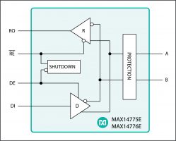
Figure 5. MAX14775E with Integrated Fault Protection
MAX22500E
MAX22500E is a half-duplex, ESD-protected RS-485 transceiver with hot-swap and fail-safe protection optimized for high speed (up to 100Mbps) point-to-point operation over long cables. It includes a configurable, integrated preemphasis circuit. This integrated preemphasis allows the user to set the optimal amount of preemphasis for a given transmission network and maximize data rates. Due to the effect of preemphasis varying with cable length and data rate, the ability to externally configure the preemphasis makes MAX22500E especially versatile for handling different networks. Retrofitting systems for different cables can be accomplished by simply changing a resistor. Note: MAX22502E is a full-duplex version of MAX22500E but for the sake of brevity only the MAX22500E part number is mentioned in the following sections.
Empirical Data from MAX22500E
The data in this section shows the effects and limits of preemphasis as demonstrated by MAX22500E. To characterize the performance of preemhpasis in an actual wired system with different cables, consider the following test setup in Figure 6. The cable under test is a commonly used EIA/TIA-568-B Cat6 twisted-pair cable of different lengths.
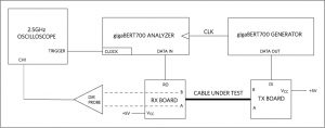
Figure 6. MAX22500E Test Setup
By running a PRBS15 signal through the cable to simulate real traffic, the effect of preemphasis can thus be characterized for different lengths of cable. The effect of ISI and preemphasis for an 25 foot cable and an 250 foot cable are presented in Figures 7 and 8, respectively.
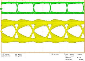
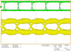
Figure 7. At 100Mbps and 25ft of cable, the signal (a) without preemphasis and (b) with
preemphasis do not differ much as the cable is too short to see significant ISI effects.
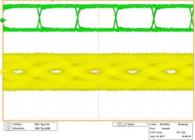
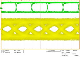
Figure 8. At 100Mbps and 250ft of cable, signal (a) without preemphasis has noticeably smaller “eyes” than signal (b) with preemphasis. At this length of cable, ISI begins to have a significant effect on signal quality, and applying preemphasis results in a clearer signal.
The point at which preemphasis begins to become effective can be seen in Figure 9 of MAX22500E with preemphasis set to the appropriate data rates, with preemphasis off, and against the original RS-485 specifications. Here, the maximum data rate that can be achieved with a bit-error rate less than is plotted against the length of the cable under test.
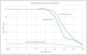
Figure 9. MAX22500E performance with and without preemphasis compared to original RS-485 specifications.
The performance seen with MAX22500E has come a long way from the 20-year-old specifications of RS-485, pushing the maximum data rate to 10x the original maximum. By applying appropriate preemphasis, the maximum data rate can be improved further, up to 20Mbps more than without preemphasis. However, as the cable becomes longer, the errors due to IR losses will begin to dominate errors due to ISI. Beyond this point, preemphasis will no longer be an effective way of increasing signal fidelity, which can be seen here as the two MAX22500E performance curves converge at 1000ft of cable. MAX22500E is backwards compatible with the original RS-485specification driving up to 1.2km (4000ft) of cable at 100kbps.
Summary
Industrial designers are constantly working to derive higher performance from the existing infrastructure. New RS-485 products offer capabilities that allow engineers to design more robust systems for increased reliability, while also increasing data rates up to 10x the original standard.
By Sean Long, Director, Applications, and Shasta Thomas, Principal Member of the Technical Staff, Applications, Industrial & Healthcare Business Unit, Maxim Integrated


