Power Supply Management Made Easy
By Nathan Enger, Applications Engineer, Analog devices Inc.
A power supply sequencer and supervisor circuit requires a number of features to make it ideal for power supply management. It must enable seamless cooperation between any number of rails, including timing and sequencing, fast voltage supervision, fault handling, and debugging. Its EEPROM memory should enable complete autonomy, and the I2C/SMBus interface needs to enable it to be interactive in real time. With flexibility, however, comes some complexity, and there are design choices that need to be made in order to achieve success. This article walks through common scenarios and how to successfully apply the features of the LTC2937 power supply sequencer and supervisor.
This article includes the following sections:
A Minimalist Circuit,
Adding Circuit Features,
Programming the LTC2937
The LTpowerPlay GUI
More Circuit Enhancements
We begin with a most basic hardware configuration, then expand to cover various improvements that take advantage of the features of the LTC2937 and add flexibility.
A Minimalist Circuit
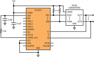
It is possible to achieve power supply management with very few external components (see Figure 1). The LTC2937 power supply sequencer and supervisor is programmed to be completely autonomous, handling sequencing up and down, voltage supervision, and fault management. A minimal number of external pull-up resistors and bypass capacitors are needed, but nothing else is required.
Schematic Connections
• Connect SHARE_CLK to VDD through a 3.3k pull-up resistor. The sequencer won’t advance if this open-drain pin doesn’t toggle.
• Connect the open-drain ENn lines through pull-up resistors to a suitable voltage (up to 16.5V). Some DC/DC converters contain their own pull-ups, and may not require an external resistor.
• Connect SCL and SDA to GND, or optionally to VDD through 10k pull-up resistors. We are not using them in this configuration, but they should not be left floating.
• All other pins can take care of themselves – leave them floating. ON, MARGB, WP, ALERTB, FAULTB, RSTB, and SPCLK all have their own built-in weak pull-ups. The ASEL1,2,3 pins will float to set the (7-bit) device I2C address to 0x44, and WP pulls itself to the write-protected state, but that doesn’t matter because the I2C bus is unused here.
Basic Functions
In this minimalist configuration the LTC2937 will derive power from the 12V input and power-up its VDD LDO regulator. When VDD rises above the undervoltage lockout threshold the device will load settings from EEPROM into operating memory (a process that takes about 2ms), then, because the ON pin pulls itself high, immediately begin sequencing up. All supplies will execute a coordinated sequence according to the preprogrammed rules stored in EEPROM.1
After the supplies are up the LTC2937 monitors for voltage excursions outside of the programmed OV and UV limits, and will detect a fault within less than 35µs of any excursion (ignoring short glitches).
When the device detects a fault, it can (depending on configuration) automatically bring down all supplies and, after a delay, try to sequence up again. It does this with no external intervention, protecting the system from damage. Note that many control behaviours are fully configurable in the EEPROM memory.
Adding Features to the Minimalist Circuit
The minimalist circuit is very functional, but it does not take advantage of all of the features that the LTC2937 offers.
In the minimalist circuit, the device is not connected to the I2C bus, so it will only follow the programming contained in its EEPROM. It is not configured to reprogram the parts on the board, so preprogrammed parts are required. If the LTC2937 contains factory default programming, it will do nothing (do no harm).
Connecting the LTC2937 to the I2C/SMBus means that advanced features, such as updating voltage and sequence rules, reprogramming the EEPROM, LTpowerPlay support, fault debugging, single-stepping, and firmware control become available. More on this later.
In the basic circuit, there is nothing to tell the device when to sequence down. Neither the ON pin nor the I2C bus command are used. When 12V falls the ENn outputs remain high because the device does not pull them low. The sequencer does not sequence down, so the supervised output regulators are on their own as far as shutting down.
Adding VPWR Monitoring
Because the minimalist circuit simply sequences up as soon as it can, and remains up until the 12V supply collapses, the likely result is an un-sequenced, unpredictable ordering of supply power-down.
There are several ways to overcome this challenge. At a minimum, we can implement a control mechanism using one of the supervisor channels to monitor the 12V voltage through a resistor divider, and cause a fault when it falls too low (see Figure 2). The fault condition, while not ideal, at least causes all ENn pins to pull low simultaneously, shutting off the supplies before the 12V voltage collapses. This is a (minimal) improvement on uncoordinated collapse.
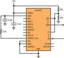
In this case, the LTC2937’s fault retry delay should be programmed longer than the expected time that it takes the 12V supply to collapse. This prevents the device from trying to start again while the supply is falling. Setting FAULT_RESPONSE[7:5] = 3’b111 (13.1 seconds) will accomplish this.
To implement a full down-sequence there are several options. The best option is to use the ON pin to command the sequencer up or down. The ON pin controls when the supplies should be on or off with its logic level. Alternatively, an I2C command can force sequencing up and down if there is a bus master to send that command. Both of these options require additional circuitry to command the device. More on this later.
The I2C/SMBus (DC1613)
The LTC2937 contains registers that make it fully programmable, and that give important status and fault information about the system as it operates. These registers are available by communicating over the I2C/SMBus interface. Any bus master that uses the SMBus protocol and the appropriate signal levels can communicate with the device. The easiest way for a user to interact with the LTC2937 is with a Windows PC, the LTpowerPlay GUI, and the DC1613 I2C/SMBus/PMBus converter.
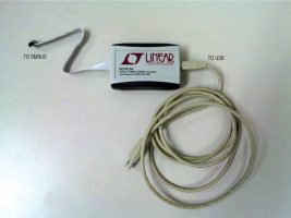
The DC1613 I2C/SMBus/PMBus converter is a small pod (sometimes called the dongle) that connects a PC’s USB connector to the I2C bus on a board (see Figure 3). Once the PC has access to the bus, it can access additional advanced features of the LTC2937 through the LTpowerPlay GUI. Providing a connector on your board for the DC1613 is highly recommended.
The DC1613 12-Pin Connector
The DC1613 has a standard 12-pin ribbon cable to connect to the board. Only a few of the 12 pins are necessary for a functioning connection. The other pins are for Analog Devices demonstration boards. Connect pins 2, 3, and 4 to the LTC2937. Pin 5 can provide 3.3V power, as we shall see. Use 10k pull-up resistors from SDA and SCL to the VDD pin of the device. Do not connect pin 1 or pins 6 to 12.
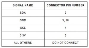
Because only four pins are required for a useful connection between the DC1613 and the LTC2937, a smaller connector may be used with a 12-pin-to-4-pin adapter.2
Power from the DC1613
It is often advantageous to communicate with the LTC2937 on the I2C bus without powering the main 12V supply. This is a safety feature that prevents accidental sequencing of supplies during programming as well as debugging before VIN is applied or after it is removed. Because the LTC2937 has a VDD pin in addition to the VPWR pin, it is simple to provide 3.3V from the DC1613 (pin 5) to the VDD of the device while VPWR is down. The simple circuit in Figure 4 accomplishes this.
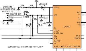
Simply add the PMOS device (M1) with its source oriented toward the LTC2937, and diode D1 to prevent current flow out of VPWR into 12V. Size R1 and R2 to turn off the PMOS when 12V is above ~4.5V, but prevent gate overvoltage. When 12V is low, the PMOS can turn on and supply 3.3V from the dongle to the device.
When the 12V supply is present, it supplies power to the LTC2937. When 12V is absent, the 3.3V supply may provide alternate power to the device and the SCL/SDA bus lines. The LTC2937 has power, and can communicate over the I2C bus, but even if it attempts to sequence up the supplies, no harm will occur without main board power.
Write Protect
The WP pin normally pulls itself up to VDD and prevents any changes to RAM or EEPROM. To enable writing, tie the WP pin to GND. Note that when the I2C bus is active, write protection prevents any writes to memory, which prevents features such as in-system programming and function control over the I2C bus.
The LTC2937 also honors the WRITE_PROTECTION register (0x00). If bit0 = 1 then the device is write protected. Use the read-modify-write technique to set the bit to 0. First read the register, which contains a key in bits 15 – 2. Then modify only bit0 → 0, maintaining the key value. Finally, write the modified contents back to the register. After the memory is unlocked the key value can be changed, if desired.
Note that both the WP pin and the WRITE_PROTECTION register must be unlocked to enable writing to the device. Include a PCB option to (temporarily) pull the WP pin to GND to enable writing to the part during in-system programming, board bring-up, and debug.
Programming the LTC2937
After the circuit schematic is configured, the LTC2937 requires register settings to set the rules of operation. With factory default register settings, the device will not sequence up. For programming purposes, the registers can be grouped into functional sets, and it is simple to program a working system with a basic understanding of the register groups.
The following example shows how to program the device for a particular set of voltages and timings. These settings will be similar, but not the same, for other applications. The data sheet gives a full explanation of registers and configuration bits.
Configuring RAM and EEPROM
The overall procedure for configuring the registers involves setting TIMING parameters, setting VOLTAGE parameters, and configuring FAULT CONTROL and OTHER functions. The following register settings show an example of the LTC2937’s sequencer configuration – a good place to start. Remember that the data sheet contains a complete discussion of all of these registers and their functions.
Note that the easiest way to program and observe registers in the LTC2937 (and many other Analog Devices parts) is to use LTpowerPlay. More on this topic later in this article.
Sequence Up Control
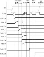
Refer to Figure 5. There are several timing parameters to set for each channel. First is SEQ_UP_POSITION. Find this parameter in the SEQ_UP_POSITION_n registers. It can take values between 0 and 1023, with 0 indicating not to sequence. Each sequencer event happens at a specified delay with a given sequence position. Multiple events can occupy one sequence position.

The second timing parameter is TON_DELAY (wait before enabling within a sequence position). Find this parameter in the TON_TIMERS_n registers. It can take values between 0µs and 655ms in 80µs increments.
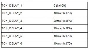
The third timing parameter is TON_MAX (allow this long for voltage to rise above its UV threshold after enable before declaring a sequence fault). Find this parameter in the TON_TIMERS_n registers. It can take values between 160µs and 655ms, or infinity.

Sequence Down Control
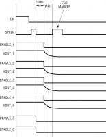
Sequence down timing is very similar to, but independent from, sequence up timing (see Figure 6.) There are several sequence down timing parameters to set for each channel. First is SEQ_DOWN_POSITION. Find this parameter in the SEQ_DOWN_POSITION_n registers. It can take values between 0 and 1023.
![]()
The second timing parameter is TOFF_DELAY (wait before disabling a channel within a sequence position). Find this parameter in the TOFF_TIMERS_n registers. It can take values between 0µs and 655ms in 80µs increments.

The third timing parameter is TOFF_MAX (allow this long for voltage to fall after disable before declaring a fault). Find this parameter in the TOFF_TIMERS_n registers. It can take values between 2.6ms and 10.5s, or infinity.

Voltage Supervisor Control
Voltage limits come in two flavors: overvoltage (OV), and undervoltage (UV). The UV limit is used during sequencing to determine when a supply is up. Both limits are used during supervision to monitor supply health.
To set voltage limits, choose the V_RANGE for each channel (1V to 6V, 0.5V to 3V, or 0.2V to 1.2V), then select OV and UV thresholds in the range.
For supplies that reside above ground, selecting voltage settings is simple. Here are some example settings:
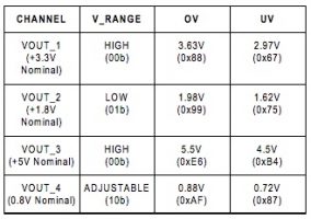
A clever use of sequencer channels is as logic handshaking during sequencing. For example, a channel may command a microprocessor to initialize before proceeding. The ENn output starts the initialization, and the returning ready signal tells the sequencer to proceed with the sequence.
For the voltage monitors connected to logic (handshaking) pins, the voltage limits can be very loose. This is because we only care to detect whether the voltages are logic 1 or not.

Fault Control
A fault happens when an expectation is violated (voltage or timing). There are several types of faults, but the two main types are SEQUENCE faults and SUPERVISOR faults. A sequence fault happens during sequencing, and cannot be masked with the MARGB pin (margin function). A supervisor fault happens when the supplies are up (done sequencing), and these can be masked by MARGB.
The LTC2937 can perform one of several actions when it encounters a fault, including turning off and staying off, or turning off and trying again. Note that turn-off means all enables go down at once; there is no down sequence during a fault.
For example we program the device to go off, wait 13.1s after all supplies discharge, then try again.
![]()
If a fault occurs, such as a voltage exceeding its programmed overvoltage limit, the device will immediately shut down all ENn outputs, disabling all supplies simultaneously (no sequence down when a fault occurs).
Other Configuration Registers
These configuration registers collect all of the remaining control and debug features. They include ON/OFF control, which faults to honor, and write protection.
![]()
This ON_OFF_CONTROL setting instructs the LTC2937 to sequence up when the ON input pin is high, and sequence down when it is low. Other bits in this register can provide additional functionality. Refer to the data sheet.
![]()
This RSTB_CONFIG instructs the device to honor all OV and UV faults, and to de-assert the RSTB output 200ms after all supplies become valid upon sequence up. Alternatively, we could set CH5 and CH6 to ignore OV faults, since we are using them as logic handshaking signals in this case. Set RSTB_CONFIG = 0xB3FF.
![]()
The WRITE_PROTECTION register contains one bit to control write protection (bit 0), and 14 bits of key value. Write protection cannot be unlocked unless the keys match. In order to unlock the write protection bit, first read the register, then clear only bit 0, then write the register with the same key. Once the register is unlocked you may write a new key value.
The LTpowerPlay GUI
Overview
LTpowerPlay is the best way to interface with the LTC2937 over the I2C bus. It provides an intuitive, flexible, and complete view of the configuration and status registers inside of many different Analog Devices parts, including the LTC2937, and provides help documentation, configuration files, and support for the part on your MS Windows PC. Figure 7 shows the LTpowerPlay tool connected to the device.
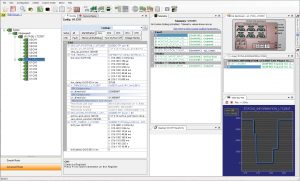
Use LTpowerPlay to:
• Program all of the registers in the LTC2937.
• Save and restore register settings in a project file, preserving configuration settings.
• Program the non-volatile EEPROM memory of the device.
• Read status information and graphically visualize what the sequencer is doing in real time.
• Debug faults and single-step the sequencer through its up or down sequence.
•Read and write configuration registers.
• Get help from online documents, videos, or a live support person.
The LTpowerPlay GUI organizes the configuration registers in groups by channel and by function (timing, voltage, etc.) Each register in the Config window pane is selectable and editable. Clicking the PCRAM button in the button bar at the top writes changes to the LTC2937 RAM. Status registers are displayed in real time in the telemetry pane. A condensed form of status information is also available in the Chip Dashboard in the upper right corner.
More information, including FAQs, documentation, and videos, are available in the Help menu.
More Circuit Enhancements
No two designs are alike, and each one calls for some customization of the basic arrangement. There are tricks that adjust the LTC2937 for a wide variety of environments with a few simple adjustments. Following are some examples.
I2C/SMBus Addresses
There are two different ways to express an I2C bus address. The address is expressed in one 8-bit byte, sent on the serial bus most-significant bit first, but the LSB in the address byte is always the read/write bit. This means that adjacent 8-bit addresses (odd/even) are the same address: even number for WRITE, and odd number for READ. For this reason the least-significant bit is often neglected in documentation, and only the most-significant 7-bits are given. This is called a 7-bit address. For example:
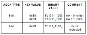
All addresses in this document are given in 7-bit format.
The LTC2937 can answer to a programmable address on the I2C bus. If there are other devices on the bus, it is important to consider which addresses the LTC2937 uses. There are three different kinds of addresses:
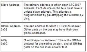
The ASEL0,1,2 pins set the slave I2C address for each LTC2937. The address can be selected from one of 27 possibilities by pulling each pin to VDD or GND, or by leaving it floating. A good approach for flexibility is to place both a pull-up and a pull-down resistor on each ASELn pin, then only populate these as necessary to set the address.
I2C Bus Buffers
Often there are multiple I2C bus voltage levels in a system. If an existing I2C bus master operates on a 2.5V or 1.8V domain, it should not be connected to the 3.3V I2C bus levels at the LTC2937 pins. The part may be damaged, or may not accept the same logic levels. Additionally, there are cases where a bus segment may be un-powered, pulling down the SCL and SDA lines, while the remaining bus segments must continue to operate. The solution is a bus buffer such as the LTC4313 (Figure 8).
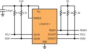
This allows the scenario where a DC1613 dongle can communicate with the LTC2937 while the microprocessor or FPGA that normally serves as bus master is unpowered.
Better On/Off Control
We have already seen a poor-man’s solution to sequencing control using one of the LTC2937’s supervisor channels to monitor the 12V input voltage. This is not an ideal solution because it does not permit a proper down sequence. It simply detects a voltage fault and shuts down everything all at once. A more robust approach uses the LTC2955 to drive the LTC2937 ON pin high or low in response to defined 12V voltage levels. This solution has the added advantage of a pushbutton for manual control. Also notice in Figure 9 that VPWR has a 10µF hold-up capacitor to power the LTC2937 while the sequencer is sequencing down. The diode prevents the hold-up capacitor from bleeding charge into the falling 12V supply.
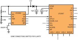
This ON/OFF circuit can also be used with the dongle power circuit in Figure 4. It will try to hold the ON pin low as long as the 12V power supply is low.
More Channels, More LTC2937s
A single LTC2937 can sequence and supervise six channels. In a system with more than six supplies, adding more devices simplifies sequencing because the sequencers communicate timing, sequence, and fault information and respond together.
Figure 10 shows the connections between LTC2937s. The following rules should be applied.
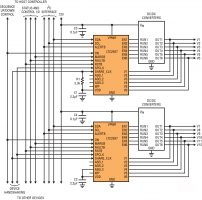
• Connect SHARE_CLK to all LTC2937s in the system. One 3.3k½ to one VDD is sufficient. All of the LTC2937s will take timing cues from the shared clock line. Do not connect SHARE_CLK to any other points in the system.
• Connect SPCLK to all LTC2937s. No pull-up is needed. All LTC2937s will take sequencing cues from the shared line. Do not connect SPCLK to any other points in the system.
• Connect FAULTB to all LTC2937s in the system. No pull-up is necessary, since each LTC2937 pulls up to its own VDD. Each device can be programmed to respond to the FAULTB line going low.
• Connect all ON pins to all LTC2937s in the system. No pull-up is necessary, since each device pulls up to its own VDD. Connecting them together helps maintain consistent state across multiple sequencers. Control this pin to command up and down sequencing.
• Each LTC2937 in the system requires a unique I2C slave address for communicating on the bus. Connect ASEL1,2,3 lines to GND or VDD (local to the chip), or leave floating to select unique addresses. Note that every LTC2937 responds to the global 7-bit address 0x36, and to the SMBus ARA 0x0C, regardless of ASEL setting.
Logic Handshake
It is possible to use one LTC2937 channel (ENn output and Vn input) as a logic handshake, instead of a power supply sequencer/supervisor. Use ENn to send a signal to a CPLD, FPGA, or other logic in the system, and use Vn to receive a logic signal when the process is complete. This is useful for devices that contain their own internal start-up circuitry that needs an undetermined time delay in the power-up sequence. The LTC2937 can simply shake hands with that device in the sequence.
Unused Channels
Tie unused Vn inputs to GND. Set the unused channel sequence position to 0 (SEQ_UP_POSITION_n = 0x0000) so it will not attempt to enable during sequencing, and set vn_ov_enable = 0 and vn_uv_enable = 0 in the RSTB_CONFIG register to prevent these OV and UV conditions from factoring into the fault decisions.
Before leaving a channel unused, consider that unused channels offer additional capability that could be used in other ways. In a sense these pins can function as general purpose inputs and outputs. Each ENn pin can provide a logic indication of a programmed register bit, and each comparator input can monitor any voltage or logic pin in the system. The I2C bus provides access to all of these functions.
Reset and Power Good
Often a system needs a reset signal that activates only when one or more power rails are not good. The LTC2937, using its many comparators, monitors the status of all of its input voltages, and releases the RSTB pin when all of the supplies are within their specified ranges (power is good). RSTB can be programmed to monitor any combination of OV and UV limits at the inputs, and can also be programmed to delay its release for a time after all supplies are good.
Use the RSTB output to reset other components of the system. The RSTB pin is not an input to the LTC2937, but its state can be read in the MONITOR_STATUS (0x30) register.
Supervising Current
The LTC2937 is a voltage sensing device. It detects voltage at its inputs. In some cases a system may need to also make sure that current is staying within prescribed limits, and respond to overcurrent conditions. With a little help from the LTC6101, the LTC2937 can do just that (see Figure 11).
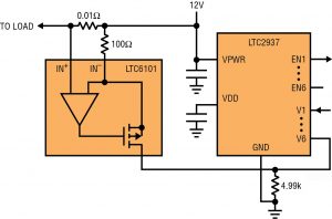
The LTC6101 is a high-side current sense amplifier that measures the differential voltage across a current sense resistor and produces a scaled, ground referenced voltage. Once the current signal is in this form, the LTC2937 can monitor for overcurrent just as it monitors for any other voltage.
Program the LTC2937 as follows (assuming CH6 is monitoring current, and 1.0A is the limit):
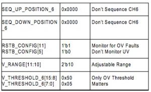
The LTC2937 will not sequence the current monitor channel, but it will respond if the current goes above 1.0A. Using the adjustable range gives the best resolution up to 1.2V at the V6 pin.
Decide on the best settings (V_RANGE and V_THRESHOLD) based upon the gain of the LTC6101 circuit. In Figure 11 the circuit gain is:

Conclusion
The LTC2937 power supply sequencer and supervisor is flexible, powerful, and easy to use. Connecting it to a system is simple, and requires few external components. It can stand alone in a completely autonomous system, and can take advantage of a few simple techniques to add powerful capabilities to any power delivery system, whether there are a handful of power supplies, or hundreds. The powerful LTpowerPlay software provides comprehensive support, from initial design-in, to EEPROM configuration, to board bring-up and debugging. With these capabilities, the LTC2937 gives you advanced control over your power system with one integrated platform.
APPENDIX A
Be a Debug Ninja
Anyone who has ever brought up a complex board knows the soul crushing smell of burning plastic upon first power-up. Something unexpectedly goes haywire on the brand new board, and now it is time to break out the soldering iron and replace parts. The subsequent debug effort takes time and distracts from the main development task. The LTC2937 is a fast, agile tool for debugging, making it much easier to avoid such situations, prevent damage to costly components, and turn a lengthy debug process into a quick audit of reported faults.
The LTC2937 detects several types of faults, and can be programmed to respond in helpful, protective ways. It can also capture information about what went wrong, pointing the way to the solution. Using The DC1613 I2C/SMBus/PMBus adapter and LTpowerPlay enable all of this.
Here are several common fault scenarios that the LTC2937 easily handles:
A Rail Shorted to Ground
Sometimes a board assembly error, manufacturing defect, or part malfunction causes one power supply rail to short to ground, preventing it from coming up at initial power-up. In this case, the power supply will not sequence up at all, and the LTC2937 will stop the sequence before anything else happens. As a result, the failed power supply can be disabled before it is damaged or something else on the board is damaged. Second, the power supply sequencer can be halted before additional power supplies are enabled, avoiding out-of-order sequencing, which could potentially damage other devices.
Sometimes an older board will encounter a defect that shorts an operating power supply rail to ground. In this case, the LTC2937 can highlight the failed supply in one easy step, even if the failure is intermittent. The status registers capture the failure information, and can be easily read to determine which supply failed.
A Rail Shorted to a High Voltage
One of the worst things that can happen to a power supply is overvoltage. If the supply is misconfigured, shorted to another that pulls it up, or if it fails in such a way that it pulls itself up to a high voltage, the result can be damage to sensitive components, and expensive board rework.
The LTC2937 detects these overvoltage conditions, and immediately shuts down all supplies under its control. As long as the system is designed to respond effectively, the overvoltage fault can be contained and quickly mitigated. The LTC2937 also indicates which supply was overvoltage, even after all supplies have been disabled. This can protect the board and still provide debug information after the fact.
Too Much Load Current
In the event that a supply cannot deliver enough current to a load, the result may be a transient brownout; the supply dips momentarily below its operating specification. Transient conditions can be tough to debug, but the LTC2937 captures momentary phenomena and stores them for later. Because the STATUS_HISTORY register flags the first thing that went wrong, we can focus on what started the cascade instead of wasting time chasing elusive downstream effects of a supply glitch.
Rail Sequencing Dependencies
A common board configuration involves one or more intermediate bus voltages on a board, powering downstream regulators. A cascade of regulators must power up in order so that downstream devices can derive power from those up stream. If sequencing dependencies are not met, there may be no power available when a downstream regulator attempts to start. In this case, the LTC2937 is very handy because not only does it make the sequence clear, as well as making it configurable and debuggable.
The LTC2937 can indicate when the upstream supply is not up in time, and prevent downstream devices from enabling. It can also be programmed to force the downstream regulators to wait until the upstream regulator is up. Fault information is readily available in the status registers. When the problem is understood, fixing it is a simple matter of reconfiguring the LTC2937 registers – either changing sequence order, or changing sequence timing. No software or system design changes are necessary.
Sequence Out of Order
There are any number of reasons that a power supply sequence may need to change after a board is assembled. Since the LTC2937 makes the sequence order and timing a matter of register configuration, it is simple to change at any point in the process. LTpowerPlay further simplifies the process by making it visual and user-friendly.
The LTC2937 has an advanced feature that enables single-stepping through the up and down sequences as they happen, making it easy to watch the system in slow motion and measure what it is doing as it comes up or goes down. The BREAK_POINT register controls this operation.
Trying to Sequence Up Before the Supplies Have Discharged
A common worry in hot-swap cards is the possibility of removing power and quickly restoring it during a plug or unplug event, either by contact bounce, or user action. This can cause the sequencer to try to go down, then up, then down again in rapid succession. If one or more supply rails on the card are not down when the sequencer attempts to sequence up again, damage can occur.
The LTC2937 features the ability to force a complete down sequence before it attempts to sequence up again. The ON_OFF_CONTROL[5] bit tells the sequencer to wait for discharge before sequencing up.
Discharge power supply output capacitance quickly by enabling the active discharge feature. Each of the six Vn inputs contains an optional active pull-down current source that is useful for bleeding off charge when the power supplies are disabled. Select this feature by setting SEQ_DOWN_POSITION_n[10] = 1’b1.
Configuring Registers for Debugging
The LTC2937 can operate completely autonomously, but when something goes wrong, it is good to stop the autonomous behavior and allow the operator to gather information. LTpowerPlay makes this easy. The appropriate response settings are contained in the FAULT_RESPONSE register.
Set FAULT_RESPONSE[4:3] = 2’b01 to immediate off and bits [2:0] = 3’b000, no retry. Alternatively, if it is better to keep the supplies enabled in the event of a fault, select bits [4:3] = 2’b00, continue instead of immediate off. Because the LTC2937 clears much of its fault information when it restarts after a fault, it is usually best to stop and wait for the user to interact before proceeding.
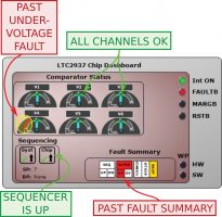
Attaching the DC1613 dongle to the I2C bus LTpowerPlay allows it to read and write registers in the LTC2937. The visuals make it very easy to see what the system is doing.3 In addition to directly reading and writing registers, the LTpowerPlay Chip Dashboard view presents device status in one simple graphic, showing comparator status and fault details in a cluster, the sequencer state, and a summary of fault and status bits. The user can use this information to quickly determine system health and operational status before parsing status registers individually. Figure 12 shows an example in which all of the power supply channels are sequenced up, and the voltages are good, but there is historical fault information about a past undervoltage event on channel 4. All of this information is immediately visible on the dashboard.
Note 1. EEPROM memory can be programmed through the I2C/SMBus, either at the factory, in a dedicated programmer, or on a system board that uses I2C bus to communicate with LTC2937.
Note 2. The Analog Devices DC2086 Powered Programming Adapter can provide the 12-pin-to-4-pin translation.
Note 3. Together with LTpowerPlay, the LTC2937 makes debugging system power supply problems much easier and more effective, reducing costly board rework, and time to market.
Figure captions:
Figure 1. A Minimalist LTC2937 Circuit
Figure 2. LTC2937 VPWR Detect
Figure 3. DC1613 I2C/SMBus/PMBus Converter
Figure 4. Power Supply Hook-Up
Figure 5. Example Sequence Up Timing
Figure 6. Sequence Down Timing
Figure 7. LTpowerPlay
Figure 8. LTC4313 I2C Bus Buffer
Figure 9. LTC2955 On/Off Circuit
Figure 10. Connecting Multiple LTC2937s Together in a System
Figure 11. LTC2937 Supervising Current with LTC6101
(Gain equation just before the Conclusion is also provided in art form.)
Figure 12. LTpowerPlay Chip Dashboard Showi


